Baluns and ununs are often treated as interchangeable “black boxes,” but selecting the correct impedance transformation ratio is critical for efficiency, bandwidth, and feedline behavior. Choosing incorrectly can lead to high SWR, excess loss, common-mode current on the coax, and disappointing on-air performance.
This guide focuses on when and why to choose a 4:1, 9:1, or 49:1 balun (or unun), with practical examples you can apply immediately.
First Principles: What a Balun (or Unun) Actually Does
A transformer at the antenna feedpoint serves two distinct purposes:
- Impedance transformation
Matches the antenna’s feedpoint impedance to your feedline (usually 50 Ω). - Current control (balancing)
Suppresses common-mode current that would otherwise flow on the outside of the coax.
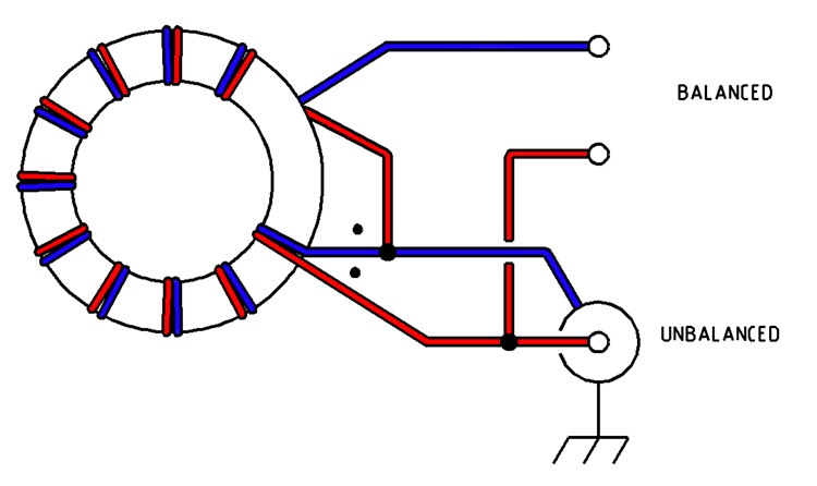
A balun is used when one side is balanced (dipoles, loops).
A unun is used when both sides are unbalanced (end-fed wires).
Ratio choice is determined almost entirely by expected feedpoint impedance, not by antenna length alone.
4:1 Balun — Moderate Impedance Transformation
When to Use a 4:1
A 4:1 transformer converts:
- 200 Ω → 50 Ω
- 50 Ω → 200 Ω
Typical Applications
- Folded dipoles
- Off-center-fed dipoles (OCFD / Windom)
- Some loop antennas
- Balanced antennas with feedpoints between 150–300 Ω
Why It Works
Many balanced antennas naturally present impedances around 200 Ω. A 4:1 balun brings this close to 50 Ω while maintaining balance and suppressing feedline radiation.
Advantages
- Lower core stress than high-ratio transformers
- Broad bandwidth when built correctly
- Works well with true current balun designs
Common Mistake
Using a 4:1 on random-length end-fed wires. This often results in:
- Wild SWR swings
- RF on the coax
- Ineffective matching across bands
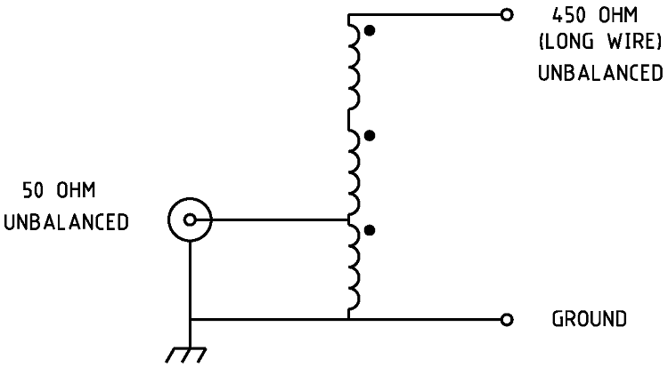
9:1 Unun — Random Wire Matching
When to Use a 9:1
A 9:1 transformer converts:
- 450 Ω → 50 Ω
- 800–900 Ω → ~100 Ω (tuner-friendly)
Typical Applications
- Random-length long wire antennas
- Non-resonant end-fed wires
- Portable and compromise installations
Why It Works
Random wires commonly present feedpoint impedances in the 400–1000 Ω range, depending on length and frequency. A 9:1 brings these values into a range most ATUs can handle.
Advantages
- Excellent for multiband random wires
- Simple construction
- Works well with external or internal tuners
Critical Considerations
- A choke at the feedline is mandatory
- Expect the tuner to do real work
- Not a substitute for resonance
Common Mistake
Calling a 9:1 an “EFHW balun.” It is not. A 9:1 is not designed for half-wave impedance points.
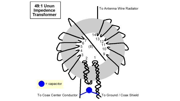
49:1 Balun — End-Fed Half-Wave (EFHW)
When to Use a 49:1
A 49:1 transformer converts:
- ~2450 Ω → 50 Ω
Typical Applications
- End-fed half-wave antennas
- Monoband or harmonic-related multiband EFHWs
- Lightweight portable HF setups
Why It Works
At the end of a half-wave radiator, impedance is extremely high—typically 2–3 kΩ. A 49:1 (7:1 turns ratio squared) provides a near-ideal match on the fundamental frequency and its harmonics.
Advantages
- Very efficient when used correctly
- Minimal need for a tuner on designed bands
- Popular for portable and stealth installations
Design Constraints
- Narrower bandwidth than 9:1 systems
- High voltage stress on the transformer
- Requires proper ferrite selection (often multiple cores)
Common Mistake
Using a 49:1 on non-half-wave wire lengths. Performance collapses outside its design assumptions.
Quick Selection Table
| Antenna Type | Typical Feedpoint Z | Correct Transformer |
|---|---|---|
| Folded Dipole | ~200 Ω | 4:1 Balun |
| OCF Dipole | 150–300 Ω | 4:1 Balun |
| Random Wire | 400–1000 Ω | 9:1 Unun |
| EFHW | 2000–3000 Ω | 49:1 Unun |
| Ladder-line Dipole | 300–600 Ω | 1:1 or none |
Ferrite and Power Considerations
Regardless of ratio:
- Use ferrite material appropriate for HF (mix 31 or 43 are common)
- Higher ratios demand larger or multiple cores
- QRP vs QRO designs differ substantially
- Always include a common-mode choke, especially with end-fed systems
Final Guidance
Choosing the correct balun ratio is not about folklore or convenience—it is about matching physics to hardware.
- Use 4:1 for balanced antennas around 200 Ω
- Use 9:1 for random wires and tuner-based systems
- Use 49:1 only for true end-fed half-wave designs
When the transformer ratio matches the antenna’s natural impedance, the result is lower loss, cleaner patterns, and a quieter shack.